
You are currently browsing the category archive for the ‘Hardware Store Tools’ category.
Here is another one for the Hardware Store Tools category. One of the most important pieces on a bicycles drive train is the rear derailer hanger. It seems like such a small, insignificant part of a bicycle, but it holds the power to really screw up your shifting performance. It also happens to be very susceptible to damage. A minor crash, or even just your bike tipping over can bend this little tab enough to ruin your ride. If the bend is fairly minor, it can be fixed. If it’s a major bend, you may need someone to replace the hanger, or if its integrated into the rear dropout, you may need someone to replace the dropout. Lets assume it’s a minor bend. You can either buy a tool made specifically for this trouble, or make your own. The following tool can be used to check your alignment, and make minor corrections. Major corrections should not be made with this tool. If major corrections need to be made, and its out of your judgment, see a professional.
Cost: $13.00 + 2 hours of time (this is assuming you have the tools, an extra axle, some extra nuts, and a small steel ruler.)
-
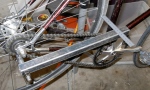
- Shown in use. Ignore the fact I’m modeling it on a fixed gear bike.

-
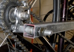
- Pic 2

-
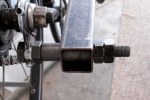
- Pic 3

-
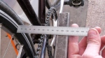
- Pic 4: Performing the measurement

-
- Pic 5

-

- Pic 6

Making this tool requires you already to have the following tools:
-bench vise
-hacksaw, bandsaw, or something else able to make a straight cut through a piece of 1″ square mild steel stock.
-scratch awl, prick punch, and center punch
-steel ruler, or vernier calipers
-Counter sink bit (optional)
-a drill with a 23/64 drill bit for metal
-hand file, or small rotary grinder
And the following supplies:
-370mm long 1″ mild steel square section. Cut to length and file smooth
-rear axle with 4 nuts. Most axles are threaded M10x1.0 just like your derailer hanger. A long bolt of this thread will also work, but good luck finding that
-22mm spacer (or combo of two) for the inside of the steel square section
-15mm spacer for the outside of the steel section
-Small steel ruler
Design:
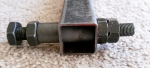
-In order to properly bend back the hanger, the tool must be threaded, and must have a nut on either side of the hanger. This way, the faces of hanger, and the inner threads remain properly aligned with each other. You can see this in Pic 2.
-The tool must have proper clearance from the axle nut, or quick release skewer nut in order to rotated about the wheel.
-spacers must be used on the inside of the square section in order to secure the section to the axle and prevent compression deformation of the section.
-The section must be long enough to measure the alignment 360 degrees around the rim.
Basic Assembly Instructions:
File all cuts smooth, and all holes to round.
1. Cut the 1″ steel square section to length if it has not already been done.
2. Drill a 12/64″ hole 12.5mm from the factory cut end of the section. You want this hole to be as close to the center of the face as possible. measure, mark, prick, center, counter sink, drill. Do the same to the opposite side.
3. File the holes round until the axle just barely fits through. This take a little patience. You want to be careful not to make the hole too large.
4. Assemble all your parts as shown in the photos and tighten every thing down to the section. Cut the axle to length if you have not already done so.
Basic Use Instructions:
1. Thread tool into hanger all the way. Measure from the edge of the tool to the rim as shown in Pic 2. Record the measurement.
2. Turn the tool counter clockwise by 90 degrees. Allow the tool to unscrew from the hanger. If needed, install the fourth nut on the cog side of the hanger and take another measurement. Record the measurement.
3. Repeat step 2 until you have four readings. This completes one turn of the tool, thus the tool has moved away from the wheel 1.0mm (1.0 pitch thread). Subtract 0.25mm from the second measurement, 0.5mm from the third measurement, and 0.75 from the fourth measurement. If your reasults are within 4mm of each other, then you are within accepted tolerances of rear derailer hanger alignment*.
4. If you are not within 4mm at your four measurement points, determine which way you need to bend the hanger, install the fourth nut on the cog side of the hanger, snug up the nuts against the hanger and bend the hanger into position. Repeat the steps above to confirm your repair.
*Thats what Park Tool recommends for a tolerance anyway. I try to get it as close to 0.0mm as possible while I have the tool on there.
This article was fist published on Sept. 24, 2008 in my personal blog Its All One Big Adventure.
Bicycle tools are somewhat expensive. If your like me and don’t like paying for labor you can do yourself, but don’t want to buy tools that you might be able to make a lot cheaper, then you’ve come to the right spot. I have made a few tools from stuff you can buy at any decent hardware store. Just about all of these tools have been made in some form or fashion before this, so I’m not claiming anything, I just want to share my knowledge.
Headset Cup Remover: This one is easy. Take 12″ piece of 3/4″ copper tubing and cut two slits about 4″ long as on-center as you possibly can. (You can also cut just one slit, but you sacrifice having even pressure on the cup when you go to smack it out.) In other words, the slits should have the same distance between them on both sides. For cutting I use a craftsman version of a dremel tool, but a hack saw and vice may work as well. When your happy with the slits, carefully separate the two prongs. Copper has a low yield strength, so take care in separating the prongs. You want to try to bend the full length of the prong as opposed to just at the joint. At the end of the tube you want the separation to be enough so you can slide the 3/4″ uncut end into the head tube and pull the prongs into the head tube until you hear the tool “click” into place. One or two hard smacks with a hammer will pop your cups right out. The copper will not damage steel cups no matter how hard you hit it, so don’t back down. The less hits to remove the cups, the more times you’ll be able to use the tool. Copper is soft and will deform when you hit it so you might be able to get two or three uses out of one piece. If you plan on removing cups on a daily basis (or more than just a few times) buy a remover tool. Once I start removing cups on a regular basis, I’ll switch over to a real tool, but for now, that length of copper tube sitting in my shop is good enough. Here’s a photo of my latest one. Its a one slit deal.

Single Slit Homemade Headset Cup Remover
Fork Crown Race Setter: A crown race must pressed or tapped down with even pressure all around it. For 1″ steel forks I use a 1″ copper sleeve and a 1″ by 24″ steel pipe. Grease the race, slide it into place and twist it while putting downward pressure. By doing this you should be able to get it started onto the crown evenly. If it didn’t happen evenly all around, start over or skip this step. Next, slide the copper sleeve onto the steertube, and then the steel tube. (A 1″ piece of steel tubing typically has an inner diameter of 1″. A 1″ steertube typically has a outer diameter of 1″ so the tool should slide right onto the steertube.) Turn the whole thing upside down, center the copper sleeve on the race, hold the fork blade and steel pipe in and tap until the pipe on the groud (or floor) until the race is fully seated. Sometimes a slam is required to fully seat the race. Here is photo of my trusty tool.

Homemade Fork Crown Race Setter
Headset Press for 1″ Headsets: This can be made using a 3/4″ stainless steel piece of all-thread, brass bushings, washers, and nuts. The bushings must be softer than steel, so brass is a good choice because it is a copper alloy, and bushings will typically come in plastic, rubber or brass. Bronze is fine too (it is also a copper alloy) so if you find bronze bushings, your good to go. The size of the bushings should be 3/4″ inner diamter, 1″ sleeve diameter, and 1-1/4″ flange diameter. A good hardware store should have this size. The press is to be constructed as shown in the photo below with the head tube and headset pieces in between the brass bushings. All headset cups are a bit different, so when setting up the press, experiment to see if the sleeve end of the bushing, or the flanged end of the bushing fits on better. More often than not, I find the flanged end applying the pressure to both the upper race and lower race to be the way to go. Assemble and slowly tighten one nut while holding the other in place.

Homemade Headset Press
Dropout Alignment Tool: Start with two steel eyebolts, four nuts, and four stainless steel washers. I use 3/8″ eye bolts that are about 8″ long. 3/8″ translates to about 9.5mm, so they are just a hair too big to fit into front fork ends. To fix this, I ground off as close to 0.25mm on each side as I could making flats on either side of the bolt. I recommend lining the flats up with the eyelets so that your eyelets are parallel when installed on the fork. I also ground the threads off the end of the bolts so they would not get caught on each other if they happen to overlap (this would happen in a serious case of dropout misalignment.) Rear dropouts are typically 10mm, so fit is not a problem. Just make sure you have them seated as far back as possible. Here is a photo of mine:

Homemade Dropout Alignment Tool
Other Frame Alignment Tools: I’ve also used a 2×4 and a piece of string to align rear triangles. Use Sheldon’s cold setting method.
Other Homemade Tools: I’ve heard of people making their own repair stands, and truing stands as well. I can imagine how this is done, but I have not done it. I bought both.
I find myself heading to the hardware store quite often to make tools from various things throughout the store. I’ve posted a few on my other blogs, but I’ll transfer them over to here when I have the chance.
Here is a fork vise I made that can be held in a regular old bench vise. Pretty simple to make if you have the right supplies and tools. You’ll need a front QR axle. This is where that old rusty front wheel comes in handy!
I have included Plans on the Downloads page

Fork Vise Secure in Bench Vise

Underside of Fork Vise

Birds Eye View
Supplies
1- 2″x 2″ steel angle – you’ll need about 85mm, but this exact dimension depends on the cones and locknuts you use.
2- 9/16″x 1-3/8″ “U” Bolts with washer and nuts
1- front quick release axle with skewer
4- front axle cones with the same Outside Diameter (OD) (old pitted cones work best!)
2- front axle locknuts
2- front axle washers
Tools
Hack saw or band saw set up to cut steel
Round File to clean up drill holes
Flat file for edges and surfaces
Bench grinder (optional)
Drill with 1/4″ bit meant for steel
Scribe, center punch and counter sink to mark and line up drill holes
Cone wrenches
Box wrenches or ratchet
Tape measure, calipers, or ruler
Instructions
Disassemble the axle and reassemble putting an extra cone on each side as shown in the photos and plan. Measure the spacing of the exterior faces of the locknuts and maintain 100mm between the two surfaces while maintaining equal axle stubs on each side. Tighten all the pieces against each other on each side. You should now have a front axle with the cones forming a rounded circular groove on each side.
Put the completed axle on one flange of the steel angle. Line up the edge of the angle with one of the exterior cones exterior face. At the other exterior cone, scribe a line on the angle at the cone exterior face. This is where you’ll cut the angle. You want the four cones to make contact with the angle flange, but you do not want the locknut (which has a larger OD) to contact the flange. See the photos and plan. You’ll end up with a piece of steel about 85mm long give or take a few millimeters.
Mark the longitudinal center-line of one of the flanges. Scribe a line parallel to the center-line offset by 3mm away from the perpendicular flange. This is the line your axle will sit on. The 3mm offset is to account for the perpendicular flange. This will make more sense when you place the “U” bolt washers on. There won’t be enough room for the washers unless you do this.
Put the axle on its seat line and center it lengthwise on the angle flange. Mark the location of the two circular grooves on the angle. Scribe lines perpendicular to your axle seat line at these marks. These are drill hole center-lines. Measure the distance between the two prongs on the “U” bolts. Mark the locations of the drill holes on the drill hole center-lines making sure they are centered around the axle seat line.
Punch mark and run a countersink bit at the drill hole locations. Make sure you have at least 8mm of steel around all the holes. Drill the holes and finish all the surfaces with files.
Assemble the tool and mark the “U” bolt prongs for cutting or grinding. (Without doing this, the prongs will be too long and will interfere with putting the tool in the bench vise). Cut the prongs and finish with a file. Reassemble and tighten down the nuts.
If you don’t have cones of the same OD, then you can grind a flat on the larger ones. Don’t bother putting it together without doing this. You’ll just bend the axle when you tighten the nuts.
You’ll find the plans on the page called Downloads. Below is a partial image of the plan. My scanner isn’t big enough for big sheets.

